
Former industrial land along the banks of the River Wear will be opened up for regeneration next year when work to build a new highway reaches completion. The section currently under construction will link the city’s Northern Spire Bridge, built in 2018, to Sunderland city centre. While the bridge was a major undertaking and created a dramatic visual legacy, phase three works pose a similarly onerous challenge, but much of the technical wizardry will be hidden away below ground and behind retaining structures.
The 2km of new dual carriageway will snake through the land that hugs the southern banks of the River Wear and is intended to open it up for redevelopment and regeneration with housing and new businesses. With much of the land formerly industrial, the quality and reliability of the ground conditions can most optimistically be described as ‘variable’.
This article was first published in the Jul/Aug 2020 issue of The Construction Index magazine. Sign up online.
Main contractor Esh Civils was awarded the £35.6m design and build contract in May 2019 and the new link is scheduled to open to traffic in autumn next year. Two subsequent phases – as yet unfunded – will ultimately see completion of the strategic corridor project in full.
A significant number of retaining structures are necessary to create space for the highway between the River Wear and the Tyne & Wear metro line; the latter borders the southern side of the land but at a much higher level. With existing land falling steeply across the site, and large industrial facilities such as the Pallion shipyard to be negotiated, retaining structures and slope stabilisation works are key to making this possible.
According to Esh Civils operations director Andrew Georgeson, the number and type of retaining structures was pared down from the indicative design in a value-engineering process after the contract award. One of the nine structures proposed has been designed out by re-profiling the earthworks, and one of the bigger undertakings – an anchored combi-wall of tubular and sheet piles – was replaced by a profiled slope secured by mesh facing and almost 1,200 soil nails.
Ground improvement works to an infilled quarry were proposed by the contractor’s designer Byland Engineering, including the installation of vibro stone columns to support a soil retaining wall (see below)
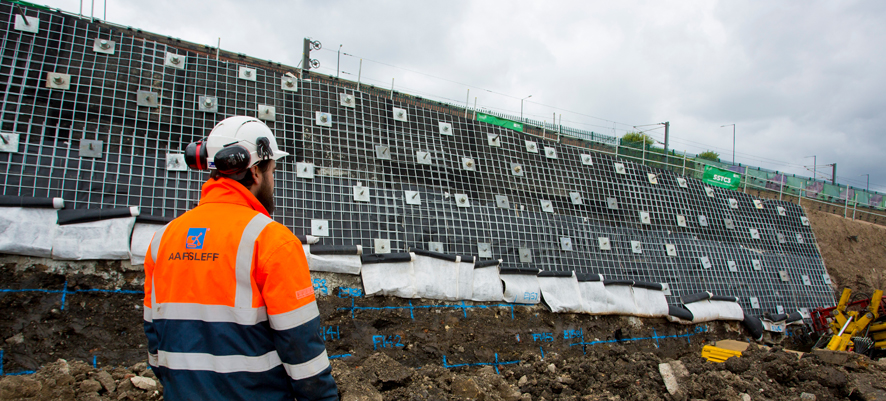
The majority of the ground improvement is being carried out by specialist subcontractor Aarsleff Ground Engineering; at the time of writing the main site operation was focussed on the soil-nailed wall which was around 70% complete, having celebrated the installation in July of the 1,000th soil nail. Aarsleff senior geotechnical consultant Dan Adams explains that it is a significant structure, extending across 1,995m2 of wall face between the new highway alignment and the metro line, rising up to 12m high and some 250m long.
It sits on the outer edge of the new highway where it sweeps through the main pinch-point between the Pallion shipyard and the metro – the focus of the majority of the ground improvement works and retaining structures on this contract. The inner edge of the highway at this point will be supported by a series of structures including a kingpost retaining wall and a contiguous bored pile counterfort wall, flanked by smaller reinforced soil retaining walls.
Adams describes the ground conditions at the site as ‘challenging’ – which is clearly something of a euphemism. “We’ve got lots of made ground overlying alluvial deposits, overlying a series of mudstones, sandstones and limestones, which are of varying strengths and conditions of weathering. There’s also a large backfilled quarry which the road passes over and which is causing challenges in terms of the quality of the fill, the depth and so on. Here the differential movement and associated settlements have to be managed and dealt with to provide something with a 120-year design life,” he says.
Aarsleff’s scope of work covers design and construction of the soil-nailed wall alternative; the installation of ground anchors to the kingpost retaining wall; design and construction of an 85m-long contiguous bored pile wall with inclined drains and a 5m retained height, and piling for an in situ concrete retaining wall.
The 85m-long wall was built in the early phases of Aarsleff’s contract and was completed before the end of 2019. Installation of the ground anchors on the other structures was just gearing up to start at time of writing; this will demand careful management due to the size and nature of the anchors required, Adams says.

Value-engineering resulted in the introduction of the soil-nailed wall, which is the largest of the structures under Aarsleff’s scope of works. This was originally intended to be an anchored combi-wall of drilled steel tubes with sheet piles in between which would have required a large embedment depth and expensive materials; by redesigning it as a soil nailed wall the contractor saved a lot of time and money, de-risked the process and created something that was more aesthetically pleasing, says Adams.
The wall is being excavated from the top down in 1.5m-high benches, he explains, with the slope first being trimmed and cut to the correct profile before the soil nails (which are up to 15m long) are installed along with the structural facing of galvanised steel mesh, which restrains the face of the slope against any movement. It is a passive system, says Adams, and it relies on movement to mobilise the bond stresses. Because of the top-down nature of the construction, all the settlements and movements occur during the construction process.
The ‘self-drilling’ soil nails are essentially hollow-stem galvanised steel bars with sacrificial drilling bits and bar diameters from 38mm to 51mm. As the bar is drilled into the ground, grout is pumped down the central annulus and into the drilling bit, then it flows back up the drill hole to keep the bore open while the nail is installed. The grout hardens and creates the bond between the nail and the ground.
So what kind of ground conditions are present in this part of the site? “It is a heterogenous mix of dead dogs and bedsteads,” quips Adams. Joking aside, he does admit that it is ‘a right mixed bag’, of cohesive made ground with granular beds, clays and other materials.

“For the very top benches we used excavator-mounted soil nailing equipment, relying on their reach to get into the working areas. As we progressed down the height of the wall we were able to form a working platform in front of the cut face on which we could place our two drilling rigs, to work cross-masted,” Adams says.
Testing to confirm bond strengths is vital due to the nature of the made ground. “Ground conditions are challenging – we develop a ground model and then we validate our assumptions with sacrificial test nails early on and throughout the works,” he adds.
Test nails are installed in exactly the same way under the same conditions as production nails; once they have cured for 7-10 days they are stressed to failure to determine the ultimate bond stresses. If the stresses don’t allow the assumptions to be validated, then additional production nails must be incorporated in the design: “We’re more than happy with the results to date, both on the sacrificial nails and the production nails,” confirms Adams.
The number of sacrificial test nails that are required depends on the nature of the ground, the type of soil and so on – and there is a minimum number according to the code. Around 2% of the production nails are tested to full working load. Adams also reveals that Aarsleff is currently discussing some additional soil-nailing works as part of the contract, in place of planned gabion walls.

The wall sits directly in front of one of the old retaining structures that has had to be incorporated into the scheme but which is assumed to have no retaining capacity. Adams explains that it was not possible to ascertain either the quality of the existing wall, or its remaining life, as it was never an adopted highway structure and hence was not subjected to regular maintenance. “We have to assume that it is basically redundant and design the new works accordingly,” he says.
The 10m-high kingpost wall is designed to be a freestanding structure, and the ground anchors that Aarsleff is installing – up to four rows – will act as ‘belt and braces’ for the old structure and any associated ground movements. The top anchors typically have three or four strands each, while those in the bottom rows are 16-strand anchors; they are all based on 220mm-diameter casing and 195mm-diameter open bore through the rock. They have a fixed length in the rock of up to 8m.
For this part of the works Aarsleff proposed a separate up-front contract during the design development to carry out full-scale trial anchors in order to demonstrate the achievable bond stresses. As Adams explains, the results from the trial anchors gave Aarsleff the confidence to subsequently make a ‘best price’ bid, and enabled the contractor to make savings on this part of the works.
Installation of the ground anchors will start in the second week of August by which time, says Adams, all sections of the kingpost wall should be in place. There are 84 ground anchors to install in the kingpost wall, which is founded on rock, and a further 30 anchors in the counterfort wall which is also under construction. The target is for the ground anchor crew to be able to move directly across from installation on the kingpost wall to the counterfort wall to eliminate downtime.
The counterfort wall crosses the backfilled quarry, which Adams says is filled with material ‘of dubious quality’ and which is a significant size, extending over an area of around two hectares and to a depth of at least 15m. It is an L-shaped section retaining wall of around 5m height built on CFA piles of 750mm diameter, up to 15m deep, and socketed 3m into the competent rock.
Ground anchors in the upstand provide additional restraining forces. These are only 10-strand anchors but they will have free lengths of up to 20m before they reach the competent rock, which brings its own challenges, says Adams: “Because we’re predominantly going through granular material, we will have to use a sacrificial steel casing with an overburden drilling system,” he explains.
Up to three rigs will be used for the ground anchor installation including two excavator-mounted rigs, one of which will sit on top of the wall and install the top row of anchors and some of the second row down. The second rig, which is capable of installing anchors to a height of about 8.5m, will work from ground level.
“The anchors have up to 16 strands andare up to 30m in length, so they are quite significant elements,” Adams says. They are factory-manufactured and supplied with a pre-grouted fixed length ready for installation. The first four permanent anchors will be subjected to on-site acceptance tests, and each and every production anchor will be tested to 1.5 times the working load.
Covid-19 restrictions have not unduly affected the contract, Adams reveals. Initially the site was shut for about a week while they put systems in place to allow staff to continue to work while physically distancing, but the nature of the company’s operations means that they are able to work more or less at full capacity, he says. N
Client: Sunderland City Council
Main contractor: Esh Civils
Subcontractor: Aarsleff Ground Engineering (soil nail wall, CFA piling and ground anchors)
Client’s designer: Capita
Contractor’s designer: Byland Engineering
Vibro-stone in Sunderland
Phase three of the Sunderland Strategic Transport Corridor includes the Pallion lower retaining wall, a 50m-long structure being built to carry the new dual carriageway writes Margo Cole

Beneath this reinforced soil retaining wall is a backfilled quarry, which underlies much of the site, with limestone bedrock up to 14m below the existing ground level. The presence of this backfilled ground caused the client’s geotechnical design engineer, Byland Engineering, to identify that some form of ground treatment would be required to limit total and differential settlements beneath the front block facing of the retaining soil wall.
The engineer designed a vibro stone column solution to limit settlement, with a total of 210 columns to be installed to depths of between 7m and 9m ahead of the retaining wall itself being built. The columns are located on a grid, with some of the columns sitting directly beneath the line of the wall face and others to either side of it. The intention is for the stone columns to improve the bearing capacity of the ground to enable it to support an imposed load of 210kN/m2.
The project’s main contractor Esh Civils awarded the contract to install the vibro stone columns to Van Elle – the first civil engineering vibro contract won by the firm since launching its new ground improvement division last year (see separate feature, page 27). Van Elle used the “top feed” method to install the 600mm-diameter columns to depths of between 7m and 9m into the firm-stiff clay that forms the historic quarry backfill. The “top feed” method involves creating a self-supporting open bore, which is filled with stone from a working platform at ground level.
In order for the specialist vibropiling rig to penetrate the firm-stiff clay fill, pre-boring was used on approximately 25% of the columns to achieve the minimum 7m design length.
The biggest challenge for Van Elle in carrying out the contract was the restricted access on the site. While this did not directly affect the vibropiling itself, it did make it difficult to do the proposed load testing to ensure the ground improvement has achieved the desired bearing strength. Van Elle suggested an alternative testing regime using plates loaded directly with kentledge, rather than a crane and kentledge frame.
This article was first published in the Jul/Aug 2020 issue of The Construction Index magazine. Sign up online.
Got a story? Email news@theconstructionindex.co.uk