.jpg)
While all eyes remain focused on the A14 Cambridge to Huntingdon upgrade scheme – still the UK’s biggest road improvement job – another, albeit smaller-scale, scheme to relieve a traffic bottleneck has just been completed a few miles north, just outside Ely.
For years the city has suffered congestion on the A142, with traffic queues stretching up to four miles. To relieve this, new £49m Southern Bypass, a 1.7km single carriageway with a viaduct crossing the river Great Ouse, was approved in 2014. Construction of the bypass, which connects the A142 at Angel Drove to Stuntney Causeway, began in January 2017.
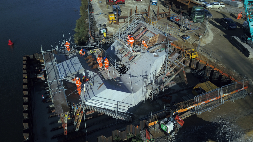
The most complex element of the project has been the 300m-long viaduct, which is supported on three slender concrete V-piers. The viaduct, designed by Buckinghamshire-based Knight Architects, is believed to be the first UK project with offset V-shaped piers and their complex geometry posed some unique challenges to the work.
To deliver this element of the works, principal contractor VolkerFitzpatrick enlisted the services of concrete specialist Sword Construction and formwork supplier RMD Kwikform.
The first of the challenges facing the team was construction of the foundations for the V-shaped piers. The section of viaduct passing over the river is supported by two of the three piers, one at either side of the river, which are themselves supported by foundations stretching into the water.
These two piers sit on piled foundations placed within cofferdams that stretched out into the river itself. However, during the planning phase, VolkerFitzpatrick identified that the loads to be placed on the cofferdam base slab would be too heavy for the ground conditions to support.
“We could not exceed 20kN/m2 surcharge,” explains RMD Kwikform engineer Ian Hawkesford. “The permanent works designers anticipated the temporary works solution would utilise the piled pier base for its foundation, and as such the cofferdam fill and cover slab around the pier was only designed for loads commensurate with small plant and equipment storage. It was not intended as a temporary foundation for the weight of the pier during construction.”
It was clear that any method to use the pier base to support the temporary works would not be feasible with proprietary equipment and would only be possible with bespoke steelwork that would require pre-stressing. “The construction programme couldn’t stand the time to design this method and it was felt that the pre-stressing element to control deflection would add an unnecessary level of risk,” explains Hawkesford.
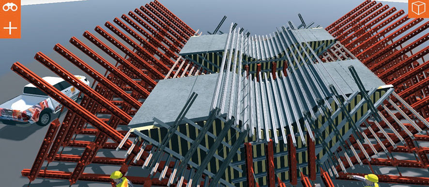
To help visualise a solution the team used 3D modelling and 3D printing technology to create a real-life, physical picture of the problem.
For this, RMD used LocusEye, a bespoke visualisation tool recently developed in-house, which allowed it to share the solution with VolkerFitzpatrick and Sword, rectifying any potential issues ahead of time.
“Locus Eye translates our traditional 3D schemes into highly realistic interactive models that can be used with virtual and augmented reality applications,” says Hawkesford. Use of 3D modelling was also essential for clash detection, since faces of formwork were prefabricated and, when lifted into place, had to mesh perfectly together, he adds.
This 3D modelling technique played a key part in the development and design phases of the project. Due to the viaduct’s very complicated geometric structure, which proved difficult to model accurately in two dimensions, RMD Kwikform created over 120 different drawings to highlight the varying dimensions and curvature of the structure, allowing a 1:75 scale model of a V-pier to be 3D-printed.
After modelling the temporary works it emerged that the optimum solution was to provide proprietary formwork propped off the cofferdam cover slab. But as the slab couldn’t cope with the full load, it was decided to pour each pier in two lifts – for which another concession had to be agreed with the architects.
“Tying through the face of the structure wasn’t permitted (see box, right) and was not possible on the internal faces; so conducting two separate pours allowed us to keep the amount of propping to a minimum within the footprint of the cofferdam,” explains Hawkesford.
After the first pour had reached a suitable strength the props were struck to release the load from the cofferdam and then the formwork was re-propped for the second pour to avoid accumulation of load. “In fact the second pour to some degree cantilevered off the first pour so minimised load into the cofferdam cover slab,” says Hawkesford.
He adds: “The most complicated and congested area was the central hole through the structure as this required two vertical formwork faces on a plan skew strutted apart for loads, with a falsework system to the ceiling of the hole as well as avoiding the inclined formwork substructure on an orthogonal plane. The visual inspection of this erected equipment required an element of contortion.”
Effective problem-solving was helped by the existing relationship between Sword Construction and RMD Kwikform. Sword, a well-known formwork contractor, has worked extensively with RMD on a number of projects, including the biomass plants in Snetterton and Tilbury, the Ipswich Tidal Barrier and the Astmoor Approach Viaduct, part of the Mersey Gateway project.
Design development
Given the difficulty of casting the bifurcated V-piers, one obvious question is why design them like that? The answer, of course, is architecture.

“When viewed from a distance the bifurcated piers give the viaduct a distinctive character that can be associated with Ely,” says Knight Architects. “The smaller spans resulting from the bifurcation allow the depth of the bridge to be minimised, reducing the visual impact of the structure within the landscape.
“Three parameters for the form of the piers determine the success of its appearance,” continues the architect’s guidelines for the design:
“The depth of the arms should be minimised to produce an elegant silhouette. The rake/inclination is important both to reduce the span above and as a figure. Viewed transversely the apertures through the piers should also be maximised.”
All this challenged the capabilities of the construction team.
The specified concrete finish also meant that formwork ties through the concrete to resist concrete pressures were originally not permitted. This prohibited simple, cost-effective methods and a concession was agreed to permit ties through the sloping top and bottom faces but not through the ends, as this face had a shadow line feature and would be the face predominantly on show.
“To prevent the ends moving they then had to be tied to the opposing pier face with formwork ties on the outside of the structure,” explains RMD’s engineer Ian Hawkesford. “This required the use of the 3D modelling to determine some 3D-shaped packers to maintain the equipment on a skewed and leaning face in a horizontal plane to facilitate the tying method.”
Knight Architects monitored the design, including compliance with planning consent conditions. A number of consultations with Atkins were undertaken prior to the submission of the planning application and final design consultant was Tony Gee & Partners.
This article was first published in the March 2019 issue of The Construction Index magazine
UK readers can have their own copy of the magazine, in real paper, posted through their letterbox each month by taking out an annual subscription for just £50 a year. Click for details.
Got a story? Email news@theconstructionindex.co.uk
.gif)