There are few simple or straightforward elements in the design of EDF’s Hinkley Point C nuclear power station project. With an estimated total cost of around £22bn and a build programme of at least eight years, the project is characterised by complex engineering on an ambitious scale.
You only need to look at the cranage mobilised to appreciate this: as previously reported in these pages, the project employs the world’s most powerful land-based crane – Sarens’ SGC-250, dubbed Big Carl, with a 5,000-tonne maximum lift capacity – to install massive prefabricated components in one go.
This article was first published in the March 2021 issue of The Construction Index magazine. Sign up online.
Just before Christmas 2020, Big Carl flexed his muscles to lift his heaviest load to date. The super-crane lifted a load totalling 575 tonnes to install the first of three enormous prefabricated steel rings which form the reinforced cylinder around the nuclear reactor.
The crane lifted the 17m-tall ring, with a diameter of 47m, into position from nearby a bunker where it had been constructed in factory conditions – one of the measures adopted by the project to improve quality.
The welded steel liner ring is the second of five pieces that make up the steel containment for each reactor, comprising a cup, the three rings and a dome. Both the inside and outer surfaces of the ring are covered with a special insulating coating applied under a turnkey contract by German insulation specialist Kaefer.
To gain access to all internal and external surfaces of this large steel fabrication, Kaefer used the Allround lightweight scaffold system from the UK division of fellow German company Layher.
It is work that has presented significant challenges as Layher’s UK managing director, Sean Pike, explains:
“The scaffolding has been designed to provide both external and internal access to the faces for coating operations and, therefore, it has had to follow the build programme very closely,” he says.
“As this process is undertaken, scaffold is being prepared for the second and then subsequent structures to follow on.”
The external structures are a particularly impressive blend of design innovation and provided an ideal demonstration of the Allround system’s suitability for highly complex installations.
“The scaffolding had to provide access to both vertical and horizontal welds for each ring – a total of some 150 linear metres,” says Jonathan Leyland, UK design manager for Kaefer. The external walls of each containment liner also feature a large number of circular protrusions which had to be accommodated by the scaffolding design.
“There is little commonality in the layout of these protrusions on each structure and, also, a wide variation in dimensions – from diameters of 2.7m to just 50mm – so it is vital that the scaffold layout is sufficiently adaptable to meet this variation. The Layher equipment has proven to be ideal,” adds Leyland.
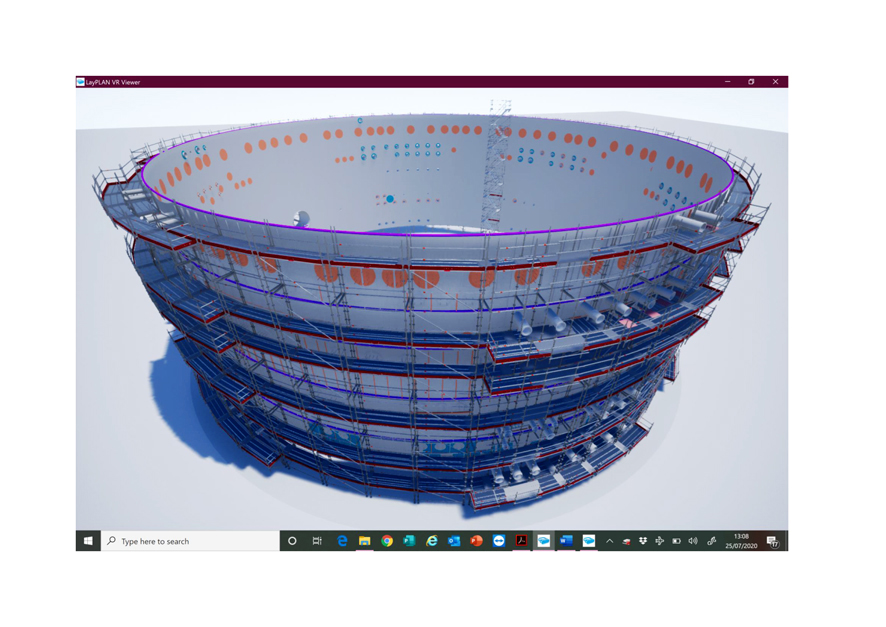
During the tender process, Layher had to design a scaffold structure to fit the irregularities of the steel containment liner before it was even built. “So, obviously, nobody really knew where the protrusions were going to go – except that they had a BIM model of this. So we exported that into our Layplan CAD software – our SIM [scaffolding information model],” explains Pike.
“We were then able to draw in SIM straight on top of their drawing and also animate that in 5D virtual reality. You could then walk in, out and around the scaffold, see where it clashed and see if you needed to move anything. We were able to do that and move things around so everything was where it needed to be – and we, together with Kaefer, of course, were the only people who could actually prove our design worked. That’s why Kaefer won that job,” says Pike.
“Once you’ve drawn that structure, you can send that information to our Material Manager software and that will then give us a very accurate parts list,” continues Pike. “You can do it by lift, you can do an animation sequence – you can do all kinds of things with it, but fundamentally it gives you a list which they can then use logistically to plan delivery to site.”
While in the past traditionalists have criticised systems such as Layher’s as being inherently less flexible than conventional tubes and fittings, the rosette design of the Layher standards, which allows multiple connections, had no difficulty accommodating the irregularities of the containment liner ring or its curved surfaces.
“Of course it could have been done with traditional scaffolding but you would have needed two to three times the amount of material,” says Pike. This would have meant a lot more transport and problems with storage. “Although it’s a big site, there’s not much laydown area,” he explains; and of course traditional scaffolding would have taken much longer to erect.
Unlike most scaffolding systems, including traditional tubes-and-fittings, the Allround system has no diagonal bracing. “Our steel decks lock the structure in plan stability and that is pretty much unique to us.
“Without that bracing going across the working face, you have unimpeded access all the way around,” explains Pike.
The Allround system will follow curves quite easily and right-angled ledgers can be used to make a splayed structure. But where a scaffold is splayed, you leave a little open triangle which, in a conventional scaffold, is usually infilled will pieces of timber scaffold board that have to be lashed down.
“With Layher you can use either our steel planks or our steel plates, which are great, and you secure them with a blue or a red pin, depending on which component you’re using,” says Pike. “But it’s still several pieces and several operations.
“Here, because there were quite a few of these to do, we manufactured specially for this job an angular steel plate that fills in the gap and fits into the U-transom so it becomes an integral part of the system – you just drop it into place.”
This bespoke component is adjustable to any angle between 15o and 45o. “The accidental result of designing that part is that it is quite useful to a lot of our other customers too,” says Pike, “and that’s a big benefit.
“The important thing with a special component is that if the customer’s got enough money in the job and there’s the potential for reuse – or using it on more than one structure as was the case here – then it’s worth investing in,” he adds.
This particular innovation was publicised in Layher’s Christmas newsletter and has already “had some take-up”, according to Pike.
Pike says that the complexity of this scaffold project could only be realised by using Layher’s 5D SIM modelling system and its virtual reality (VR) viewer. “This saves time and helps to optimise logistics and labour – and the customer sees what they are getting beforehand,” he says.
This article was first published in the March 2021 issue of The Construction Index magazine. Sign up online.
Being able to view virtual structures in fine detail means that both the layout and movement through the structure can be assessed and modified long before equipment arrives at site. Layher estimates that this has reduced the amount of scaffolding that may otherwise have been required for the project by some 15%.
Got a story? Email news@theconstructionindex.co.uk