
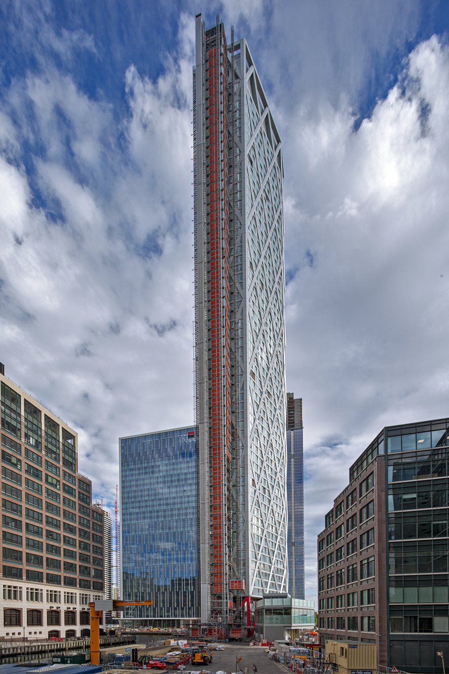
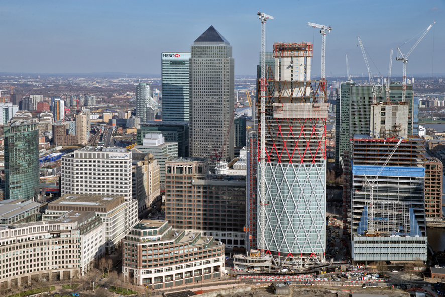
At sixty-two storeys high a tower that is due to complete next spring at London’s Canary Wharf provides an impressive 225m-tall bookend to Middle Dock, right in the eyeline of those emerging from the area’s main underground station. With its marketing campaign set to launch before the end of the year, the Newfoundland tower will be one of the first build-to-rent schemes on the Canary Wharf estate, and is claimed to be the tallest of its kind in the UK.
The tower occupies a compact, diamond-shaped site at the end of the dock, one which was initially earmarked for a series of different schemes – a hotel, then residential properties for sale – before the decision was taken to build-to-rent and address changes in the residential market.
The site itself did not form part of the original estate of Canary Wharf Group, but had been purchased more recently. In fact the tower’s moniker actually owes more to the fact that it was ‘new-found land’ than to the Canadian province of the same name.
But before construction of the main tower could begin, substantial enabling works had to be carried out and this was let as a separate contract, as John Crack, associate director of structural at Canary Wharf Contractors explains:
“It is a very small and complex site, and although the road layouts in front of it have changed over the years, the utilities were never relocated,” he says. Hence a figure of ‘several million’ had to be expended to divert the services. Canary Wharf Contractors senior project manager David Johnson reveals that this included medium-pressure gas mains, surface water sewers, and a whole raft of telecoms cables, some of them serving extremely sensitive customers such as trading floors in the neighbouring towers.
When it came to the main tower, the combination of the building height, the constrained site, and its location at the end of the former dock straddling the Jubilee Line tunnels that pass directly below, created some tough challenges for the design and construction team, says Crack.
“Although the rail lines emerge from the station some distance apart, they converge as they turn the corner at the end of the dock and head off under the river towards the next station,” he explains. The location of the building within the site footprint also complicated matters – it was considered important that the structure was symmetrically placed at the end of the dock to increase its visual impact from the station, and this meant that there was very little wiggle-room around the sensitive rail tunnels.
As a result, the building has to straddle the two tunnels, and it proved unavoidable that the piles that were carefully sunk between the tunnels extend within the 3m exclusion zone. “In fact we actually had to negotiate a ‘lease’ for this space from Transport for London,” Crack reveals, adding that the negotiation process took a long time to complete due to the sensitivity of the proposed construction work.

A series of trial bores had to be carried out to one side of the tunnels, with the bores mimicking the size and proximity of the proposed piles. Inclinometers and other measuring devices were used to monitor the impact that the groundworks had on the tunnel and ensure that it was within the required tolerance.
To complicate the groundworks even further, the positioning of the tower block was also constrained by the presence of a Grade I listed structure on the eastern side of the site that dates from the early 19th century.
The so-called ‘banana wall’ is a section of the former southern wall of the West India Export Dock; a survey in 2001 revealed that the brick structure had a banana-shaped cross-section that was intended both to improve the structural stability of the wall and to accommodate the profile of ships’ hulls. It is also noted as the earliest known example of reinforced brickwork, and the pile installation comes within a metre of this heritage asset. The secant piles that surround the basement box to make it watertight are positioned right up to the back of the structure, which could not be damaged in any way.

A total of 272 secant piles and 56 foundation piles were installed below the Newfoundland tower. The main bearing piles are 60m long and founded in chalk - Crack explains that in the east of London there is no London Clay, so ground conditions at the site consist of Lambeth group soils overlaying the Thanet sands, into which the main bearing piles extend.
Most of the bored, reinforced concrete foundation piles are 2.4m in diameter, confirms WSP associate director Chris Gosden, with just one having to be slimmed down to 2.1m, to fit between the tunnels at their closest point. Even with the trial bores successfully completed, the installation of the permanent piles still had to proceed with a great deal of care. Tolerance for pile installation was +/-25mm on position at ground level, and 1:250 on verticality over the length of the pile, using a sonic calliper to verify the latter.
The outer edges of the piles come within 2m of the Jubilee Line tunnels, which are located at around 23m below ground level; each pile took 48 hours to complete, but trains were able to continue unaffected throughout the process. Tunnel inspections were carried out at night after the trains had stopped running.
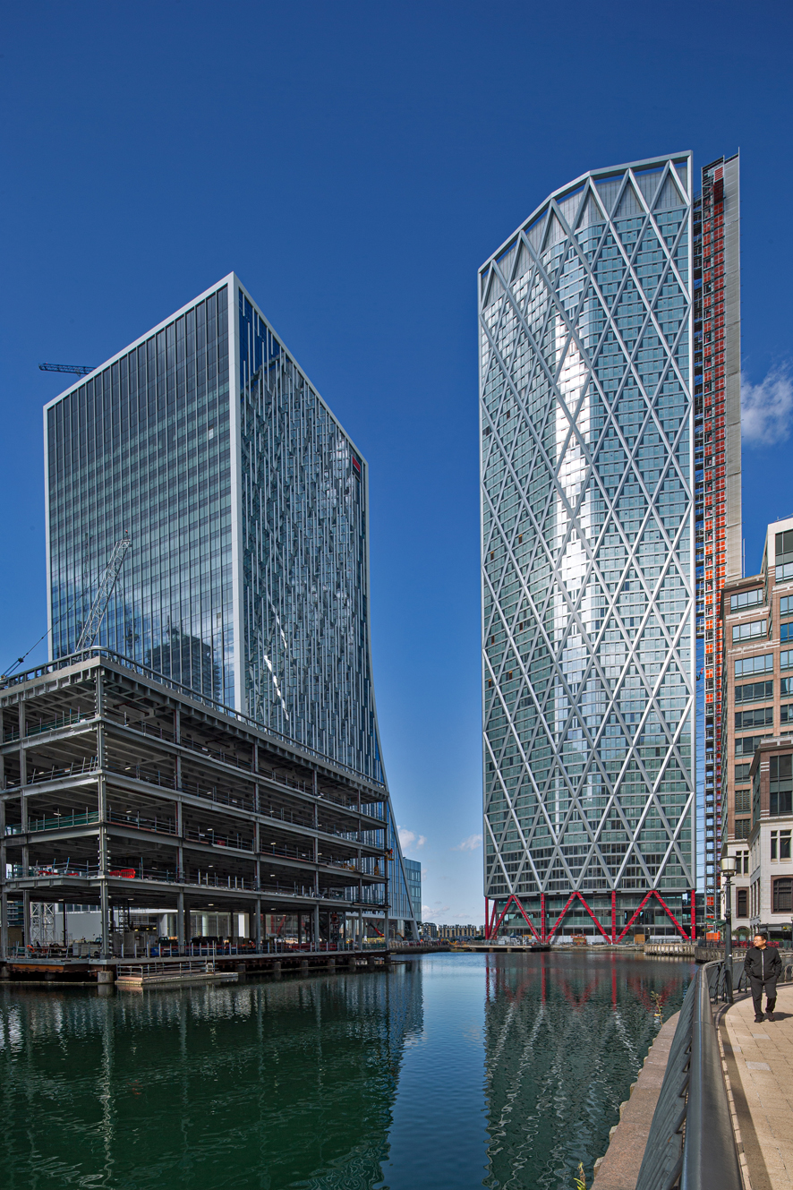
A 3m-thick concrete raft was then constructed on top of the piles to straddle the tunnels, carrying the load of the building into the ground on each side. Clearly the small building footprint – 58m by 26m at its widest point – limited space for foundations. This combined with a tall building pointed to the need for lightweight construction, and it was largely this that drove the design of the steel diagrid structural frame, reveals Gosden.
“We did consider a number of other options, but they all had drawbacks,” he says. “Weight would have been an issue with the concrete diagrid option; the Vierendeel alternative would have needed thicker walls in the concrete core. Ultimately we kept coming back to the steel diagrid, which offered the best solution both from an architectural and a structural point of view.” Keeping the concrete core to a minimum also frees up more space for the apartments themselves.
Analysis was required to establish the optimum raking angle for the main diagrid members to ensure that they work efficiently – too shallow an angle and the members act more like beams; too steep and they act as columns.
“The diagrid exoskeleton provides excellent stability,” says Gosden. “The triangles resolve the forces and are braced, with the structure creating a natural transfer system that allows the loads to be directed to the eight discrete founding locations. With this system, the core walls can be relatively slim as they act like a column.”
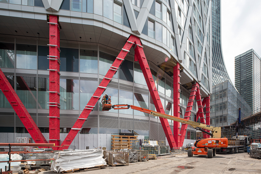
The lowest level of the building is referred to by the team as the ‘mega-diagrid’ – an enhanced version of the diagrid structural form designed to enable the load of the building to be distributed into the piles via eight 50-tonne steel grillage elements that are essentially giant spreader plates, transferring up to 10,000 tonnes into the foundation piles.
These grillage members were each custom-designed for a specific location to suit the irregular pile locations. The main members of the ‘mega-diagrid’ are 750mm rectangular hollow sections made out of 120mm-thick plate, and they are filled with concrete to increase their stiffness. Each one weighs around 35 tonnes and lengths are up to 17m for the longest.
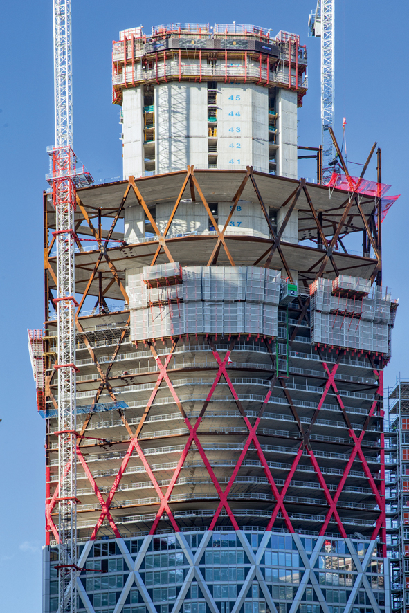
Above the mega-diagrid, the main tower has been designed in a hybrid form, with a combination of systems chosen to enable rapid and efficient construction and minimise downtime for subcontractors. Typical section size of members in the diagrid is 600mm square, with lengths up to 14m; section size reduces at the higher levels of the building.
The diagrid structure is arranged in four-storey sections between node connections, each incorporating 54 members, including steel beams at the node floors that link the outer grid to the concrete core. This is intended not only to assure the stability of the diagrid, but to transfer wind forces between the two elements of the tower. According to Gosden, wind-tunnel testing revealed that the presence of another tall tower just south of Newfoundland will increase the wind loading it experiences, creating wake buffeting that the tower needs to be designed to accommodate.
Precast floor planks span between the steel beams at the node floors, and are finished with an in situ concrete topping. Work at each node floor was carefully programmed into quadrants, with the steel erectors installing the steel beams in the first quadrant, then moving round to the subsequent quadrant, freeing up the first one for the precast plank installation.
Once each node floor was completed, the three storeys in between were built as in situ post-tensioned concrete floors. This work was carried out in the shelter of the node floor above, while at the same time the steel erectors could continue installing the diagrid elements above it, to form the subsequent four-storey diagrid lift.
The post-tensioned floors that are used for the intermediate storeys are lightweight and able to span further, making them ideal for this application. Cladding installation, electrical and services fit-out could then follow on behind. Throughout the main construction programme, progress averaged one floor per week, Crack confirms.
Steel for the main structure – some 10,000 tonnes in total – was fabricated and erected by a joint venture of Victor Buyck and Hollandia Structures. The constrained nature of the site, and its location at the western side of the Canary Wharf financial district, meant that there was little room for materials storage.
The site is bounded by the dock on one side, and by one of the main roads accessing the Isle of Dogs on the other, hence just-in-time delivery was crucial, in particular for the larger steel members and node connections.
The structural steel elements were brought by road from fabrication plants in the Netherlands and Belgium, and delivered to a storage area just downstream of the Dartford Bridge. From there, deliveries were made to site by road as required.
The plan footprint of the site was not the only physical restriction that impinged on construction – the building is also on the flightpath for nearby London City Airport, as a result of which flat-jib tower cranes had to be used, rather than the luffing jibs that would have been preferred.
Two external Terex tower cranes were used to service the main building construction - one being allocated for use by the steel erectors and the other by the concrete team – with a bank of five construction hoists supporting delivery of all other materials, personnel and equipment. “We have two people hoists, two goods hoists, and the fifth is a ‘mammoth’ hoist for all the larger items, and this enabled us to limit our reliance on the tower cranes,” explains Crack.
Larger items included the unitised cladding system that is used on the tower, the majority of which was brought up in the large hoist and wheeled into position for installation from the inside. The column lifts for the diagrid were up to 22 tonnes and the node lifts were up to 18 tonnes.
Work on the project began in 2014, with two years of utilities diversions involving the relocation of telecoms, power, gas, water and sewers from the building footprint back to the adjacent highway.
Piling started in the autumn of 2015 with more than 300 piles installed in total - including some of the deepest piles in London extending up to 60m below ground. By spring the following year, excavation of the basement had begun, with a total of 18,000m3 of spoil having to be removed.
Construction of the basement was finished at the start of 2017 and work on the concrete core began, and by early summer of the following year, all 60 floors of the concrete core were complete and the structural floors were topped out in November 2018.
With trades still at work in the upper storeys of the building, furnishing of the apartments lower down has already begun, and next spring the tower will be handed over to Canary Wharf Group’s rental partner Vertus to finish preparing the 636 apartments for release to the market.
Owner: Canary Wharf Group
Main contractor: Canary Wharf Contractors
Architect: Horden Cherry Lee Architects
Detail architect: Adamsons Architects
Structural engineering/facade engineering: WSP
Subcontractors:
• Balfour Beatty Ground Engineering (piling)
• Expanded Structures (concrete)
• Victor Buyck Hollandia JV (structural steelwork)
• Schneider (cladding)
• Briggs & Forrester (MEP)
In numbers
• 6km of piles
• The equivalent of seven Olympic-sized swimming pools were excavated to form the basement
• 5,000 tonnes of reinforcement fixed
• 30,000m3 of concrete cast to form the basements, core and structural floors
• 14,000m2 of precast concrete plank installed
• 9,500 tonnes of structural steelwork erected
• 4,500 cladding panels erected
• An average of 550 operatives on site every day
This article was first published in the September 2019 issue of The Construction Index magazine (magazine published online, 25th of each month.)
UK readers can have their own copy of the magazine, in real paper, posted through their letterbox each month by taking out an annual subscription for just £50 a year. Click for details.
Got a story? Email news@theconstructionindex.co.uk